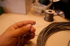
First photos are a thermistor string, second set are for individual thermistor setups.
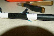
Finally, the completed thermistor is covered with a bit more protection. This step here has changed quite a bit over the years. These days a copper tube filled with a thermally conductive epoxy is the used in place of this heat shrink / silicone combo.
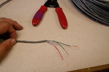
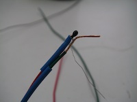
For the individual thermistor type such as for air temperature, soil surface temperature or riverbed temperature a two-pair cable is generally used. This photo shows the in-situ end stripped back and ready for the addition of two thermistors (one per wire pair). I generally pair them as red/green and black/white.
Before sodering the thermistor on, be sure to add the heat shrink.
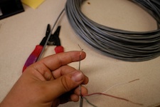
Take one of the wires from the cable in your left hand (if you're right handed) and a bit of the thermistor lead. Hold these two and then with your free hand (in my case, the right hand) grasp the other thermistor lead and wrap it around the copper wire of the main cabling. Doing this should give you a soild mechanical bond in addition to the soldered bond.
This photo illustrates a good mechanical connection between thermistor lead and cabling wire. It is now ready to be hit with a bit of solder.
You can see in this photo the soldering of the first lead is finished. Next, the excess wires are trimmed. A small pair of wirecutters is perfect for this task. The copper wire can be cut above the thermistor and the thermistor lead should be cut at the far end of the soldered connection.
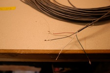
Now you're ready to connect the second leg. I find it easiest to make a big half-loop like this. If you start with too tight of a loopy bit it is harder to tightly pull the thermistor against in this case, the white wire. But that is what you'll do next. After making the large half-loop pull the free thermistor lead towards the first lead. This makes it easier to cinch the connection tightly. Once it's tight, complete a full loop. Then you should be able to do several more loops threading the thermistor lead like through the head of a needle.
Just showing how close and nicely you can do things with that second thermistor lead. At this point you are ready to hit it with a bit more solder and call it good.
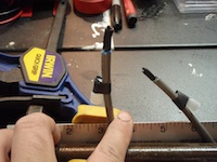
The previous photos are the 2008 version of the 2 wire pair thermistor. I have iterated a bit and this is the 2009 model. I redesigned with an eye towards making them more bombproof. I didn't think the silicone was bombproof. Now this is the nearly final step. The gray cable leads are much shorter, more similar to what is done with the direct-burial telephone cable method. Next, the a copper tube is put over the top, heat-shrinked into place and then the pacakge is filled with a thermally conductive epoxy.