First photos are a thermistor string, second set are for individual thermistor setups.
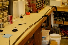
This photo shows 12 pair direct burial telephone cable laid out on a work bench ready for thermistor string manufacture. The thermistor locations have already been marked.
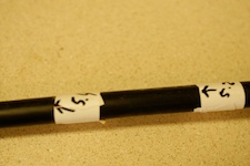
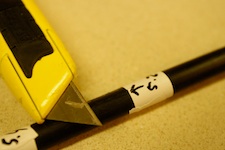
This picture shows the window location. Window marking can happen in any direction, you could start at the bottom of the cable and work up or work from the top end to the bottom. That is for labeling. For the wire selection process it is very important to start from the top end of the cable and work towards the bottom. The arrows in these photos point to the as-built position of the thermistor. So in this case in the photo, the window that will be cut in the cable will have the right side at the arrow. The left side will be 2 cm or so to the left.
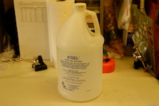
This is a general supply. D-Gel is the product name of a citrus-based solvent that works well to clean the chemical compound that keeps the water out of the direct burial cable.
In the picture foreground, the cable end is being opened. This end will connect to the mutliplexer / data logger. In the background you can see several thermistor locations on the cable ready for the next step.
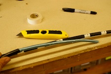
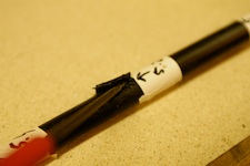
This picture shows the three cuts made in the window opening process. In this case, the window references the view to the inside of the cable at this point. You can see the slice immediately to the left of the 5.2 arrow. That is roughly (+-2mm or so accuracy) where the thermistor bead will be located. the +-2mm references error with respect to where precisely the thermistor is soldered to the cable.
After the window has been cut it needs to be opened. Use a slender screwdriver to pry open the hard plastic casing.
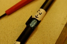
Shown in this picture, the plastic casing has been opened to form a window but there is another layer inside. Carefully slice with a knife this foil length-wise in the middle of the open window. You should be able to peel this back with a combination of the screw driver, a small pliers and the knife (if neccessary).
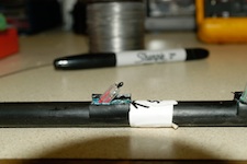
Seen in this photo, the window is completely open and two wires have been selected. Snip them with a small wire cutter next to the arrow and then use wire strippers to expose the copper center. Use a volt-ohm meter on the continuity tester setting to connect these two wires here with the corresponding wire pair at the top end of the cable. Mark them with colored tape so they are easier to identify.
Fast forwarding a couple of steps, this photo shows the thermistor connected to the telephone cable. In final position, the wires will be bent back to lay flat with the cable. That action, as you can see in this picture, will put the thermistor bead very close to the design position at the arrow.